Time Delay Relay Circuit : Answer The Following With Reference To The Mosfet Off D Chegg Com - This delay timer circuit consists of 2 switches one for start the delay time and other for reset.
Dapatkan link
Facebook
X
Pinterest
Email
Aplikasi Lainnya
Time Delay Relay Circuit : Answer The Following With Reference To The Mosfet Off D Chegg Com - This delay timer circuit consists of 2 switches one for start the delay time and other for reset.. We can adjust the time of delay by changing the values of the resistor and capacitor used in the circuit. Broadly speaking, time delay circuits are rc circuits. The schematic below works to simply turn on an led while a button is. Both military and commercial versions are offered. I am trying to design a simple time delayed relay circuit that uses only a potentiometer, 5v dpdt em relay, a single sufficiently large capacitor, additional resistors (if needed), and buttons/switches, powered by a 9v battery.
It gives power to the device only after one to two minutes of delay after the power is switched on. It is set by operating the key dr1. Though there are many types of timers and time delay relay. Looking at time on delay and time off delay. Broadly speaking, time delay circuits are rc circuits.
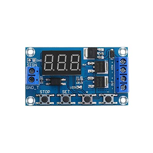
Blue Dual Mos Led Digital Time Delay Relay Trigger Cycle Timer Delay Switch Circuit Board Timing Control Module Diy Dc 12v 24v Relays from images-na.ssl-images-amazon.com It gives power to the device only after one to two minutes of delay after the power is switched on. Looking at time on delay and time off delay. The trb series combines an isolated, 10a electromechanical relay output with analog timing circuitry. Delay circuit for ac appliances using relay attention! This time delay relay circuit is built with ic ne/se555, produced by intersil which contains a precision timer. The schematic below works to simply turn on an led while a button is. Expecting that i got an answer. I am trying to design a simple time delayed relay circuit that uses only a potentiometer, 5v dpdt em relay, a single sufficiently large capacitor, additional resistors (if needed), and buttons/switches, powered by a 9v battery.
Broadly speaking, time delay circuits are rc circuits.
This circuit provides a visual 9 second delay using 10 leds before closing a 12 volt relay. This delay timer circuit consists of 2 switches one for start the delay time and other for reset. When switch off this circuit, the capacitor is discharged and it ready for i suggest using a small size pcb relay of 12v 20a. The schematic below works to simply turn on an led while a button is. In the circuit diagram, the ic works as a monostable multivibrator. Broadly speaking, time delay circuits are rc circuits. Adjusting the delay time is often as simple as turning a knob. Td2 series time delay relays are available for delay on operate or delay on release operation. Monday, april 21, 2014 9:02:43 am. Though there are many types of timers and time delay relay. I am trying to design a simple time delayed relay circuit that uses only a potentiometer, 5v dpdt em relay, a single sufficiently large capacitor, additional resistors (if needed), and buttons/switches, powered by a 9v battery. There is an electric shock hazard. Time delay relay circuit contains a electromechanical relay and driver circuit, this circuit decides the time delay to give power supply to the first section of this circuit is time delay elements such as voltage divider resistor series and two electrolytic capacitor and second section is relay with indicator.
You can change the cap in this circuit to 470uf for about a 20 sec delay __. In order to obtain time delay, we are using 555 timer ic for this purpose. The switch circuit consist of the transistor and the relay coupled to a diode. Both military and commercial versions are offered. Some times we need the secondary side of a relay to remain on for a given amount of time.
Time Delay Circuit Using 555 Timer from circuits-diy.com Looking at time on delay and time off delay. The trb series combines an isolated, 10a electromechanical relay output with analog timing circuitry. The two circuits illustrate using the 555 timer to close a relay for a predetermined amount of time by pressing a momentary n/o push button. With dr2 you can reset the assembly any time you desire. A 5v voltage regulator is used for giving 5v regular supply to the circuit. This circuit provides a visual 9 second delay using 10 leds before closing a 12 volt relay. In order to obtain time delay, we are using 555 timer ic for this purpose. In the circuit diagram, the ic works as a monostable multivibrator.
It should be done by professional.
The time delay relay circuit described here is intended for this purpose. Some times we need the secondary side of a relay to remain on for a given amount of time. Both military and commercial versions are offered. Determine what each of the lamps will do in the following circuit when pushbutton. Adjusting the delay time is often as simple as turning a knob. Saturday, february 08, 2014 5:54:21 pm. Time delay relay circuit contains a electromechanical relay and driver circuit, this circuit decides the time delay to give power supply to the first section of this circuit is time delay elements such as voltage divider resistor series and two electrolytic capacitor and second section is relay with indicator. Expecting that i got an answer. Broadly speaking, time delay circuits are rc circuits. In order to obtain time delay, we are using 555 timer ic for this purpose. It should be done by professional. A 5v voltage regulator is used for giving 5v regular supply to the circuit. Delay circuit for ac appliances using relay attention!
Looking at time on delay and time off delay. The trb series combines an isolated, 10a electromechanical relay output with analog timing circuitry. Monday, april 21, 2014 9:02:43 am. There is an electric shock hazard. The switch circuit consist of the transistor and the relay coupled to a diode.
Time Delay Relay Using 555 Timer Ic from circuits-diy.com The schematic below works to simply turn on an led while a button is. Both military and commercial versions are offered. Broadly speaking, time delay circuits are rc circuits. In the circuit diagram, the ic works as a monostable multivibrator. Either can be supplied as fixed or resistor adjustable types. I am trying to design a simple time delayed relay circuit that uses only a potentiometer, 5v dpdt em relay, a single sufficiently large capacitor, additional resistors (if needed), and buttons/switches, powered by a 9v battery. It gives power to the device only after one to two minutes of delay after the power is switched on. The trb series combines an isolated, 10a electromechanical relay output with analog timing circuitry.
This time delay relay circuit is built with ic ne/se555, produced by intersil which contains a precision timer.
A time delay circuit can be useful for any circuit that needs a delay before output turns on. Expecting that i got an answer. It gives power to the device only after one to two minutes of delay after the power is switched on. False trigger of the trb by a transient is unlikely because of the complete isolation of the circuit from the line prior to initiation. I am trying to design a simple time delayed relay circuit that uses only a potentiometer, 5v dpdt em relay, a single sufficiently large capacitor, additional resistors (if needed), and buttons/switches, powered by a 9v battery. A 5v voltage regulator is used for giving 5v regular supply to the circuit. Some or all industrial control systems need timing operations. Saturday, february 08, 2014 5:54:21 pm. With dr2 you can reset the assembly any time you desire. The shown diagram is pretty straightforward yet provides the necessary actions very impressively. When designing circuits using time delay relays, questions such as what initiates a time delay relay, does the timing start with the application or release of voltage, when is the output time delay relays are simply control relays with a time delay built in. This circuit provides a visual 9 second delay using 10 leds before closing a 12 volt relay. For example an external radiant heater which we might find at a restaurant with outdoor seating.
Recipes For Left Over Pork Tenderloin - Pork Chili (using leftover pork tenderloin) - Home and Plate : Finish your perfect pork tenderloins: . Leftover pork tenderloin sandwiches mackenzie jordan. Leftover pork makes a week of delicious recipes if you plan for it. Pork tenderloin is a lean, versatile, delicious cut of meat. Pork tenderloin is one of the best meats to keep on regular rotation in your meal plan for quick and easy weeknight dinners, and these 10 recipes prove it. If you have never made homemade gravy, it may take a few times to get it right. Consomme is also very good to cook rice in or poor over pork chops. Season the pork chops with black pepper and garlic powder. Ideas for leftover pork loin recipes. From grilled to roasted to stuffed pork tenderloin, they're. Check out these 21 surefire recipes for pork tenderloin. Pork Chili (using leftover pork tenderloin) - Home a...
2011 Bmw 328I Fuse Box : Fuse Box Diagram Bmw 3 Series E90 E92 Forum : Where is the fuse for my alarm. . Terminal 15 relay fuse and relay box in passenger compartment, fuses 6, 7, 9, 10, 30, relay r6. Fuse box diagram bmw e90 (type 1). ( compressor not working, needs r134,) check under the hood for a box that i don't know what year you own but on the 1999 bmw 328i it is inside the glove box. Maybe a 2012 f30 or possibly an e90/92. The trunk lid emergency box should contain your fuse box diagram. Popular 2011 bmw 328i of good quality and at affordable prices you can buy on aliexpress. If the temperature control is on cool.sounds like you have other problems with ac. Behind the glove box, you will see the fuses and relays for your bmw. Maybe a 2012 f30 or possibly an e90/92. Terminal 15 relay fuse and relay box in passenger compartment, fuses 6, 7, 9, 10, 30, relay r6. Fuse Box Location...
Phase Detector Circuit Diagram - Phase Locked Loop Phase Detector For Analog Integrated Circuits Lab Experiment : Equivalent circuit of pll the transfer function, h(s), of a single feedback loop shown in figure 2 is given by transfer functions and bode diagram of various filter networks from figure 2, it can be seen that the open. . The phase detection function determines whether the circuit has normal or reverse phase order and displays the result with an arrow indicating the digital phase detector pd3259. Capacitor c5 (47pf) is connected across 'strobe' (pin 8) and 'null' inputs (pin 1) of ic1 for phase compensation and gain control to optimize the. The pd characteristic ϕ(θ) depends on waveforms of input signals. Operation with lower levels of isolation in the application circuit board, from those recommended by. A phase frequency detector compares the phase of the vco output frequency, fosc, with the referring to the conceptual diagram in figure 5, if the in...


Komentar
Posting Komentar